Performance of electric double Layer capacitors using annealed activated carbons from phenolic resin as electrodes
Negar Amini*, Chunhong Lei*, Steve Tennison, Constantina Lekakou
DOI10.36648/2470-9905.6.3.156
Negar Amini1,3*, Chunhong Lei2,4, Steve Tennison3, Constantina Lekakou4
1 DBSL, De Asselen Kuil 12, 6161 RD Geleen, The Netherlands
2 Materials Centre, Department of Chemistry, University of Leicester, University Road, Leicester, LE1 7RH, UK
3 Carbontex Ltd, 62 Farleigh Road, KT15 3HR Addlestone, UK
4 Department of Mechanical Engineering Sciences, Faculty of Engineering and Physical Sciences, University of Surrey, Guildford GU2 7XH, UK
*Corresponding Author:
Negar Amini
DBSL, De Asselen Kuil 12
6161 RD Geleen
The Netherlands
Tel: +31 611856569
Email: negar.amini@dbsl.nl
Received: September 14, 2020; Accepted: September 30, 2020; Published: October 07, 2020
Citation: Amini N, Lei C, Tennison S, Schaaf VAM, Lekakou C (2020) Performance of electric double layer capacitors using annealed activated carbons from phenolic resin as electrodes Struct Introduction Chem Crystallogr Commun Vol.6 No.3 DOI: 10.36648/2470-9905.6.3.156
Abstract
The effect of annealing at different temperatures on the structure and electrochemical performance of the activated carbon material derived from phenolic resin is studied. Annealing the carbon material up to 1800 °C increased the electric conductivity of the activated carbon from 2.6 to 8.3 S/cm. The electrochemical performance analysis of the annealed carbon materials as electrodes in electric double layer capacitors with organic electrolyte revealed that the thermally treated carbon materials deliver greater power densities (up to 30 kW/kg) at high currents. Moreover, the annealed carbon electrodes showed better capacitance retention at high current densities.
Keywords
Supercapacitors; Heat treatment; Activated carbons; Electrochemical performance.
Introduction
Electrochemical double layer capacitors (EDLCs) or supercapacitors are energy storage devices with high charge/ discharge rate and high power and life time characteristics. They can be used as alternative or complementary power sources in various applications such as portable electronic devices, back up power systems, pulse power devices, and hybrid electric vehicles [1].
Activated carbons are the most widely used materials as electrodes in EDLCs because of their high surface area and relatively low cost [2]. Activated carbons are derived from carbonisation of either natural sources, such as coconut shells, wood, pitch or coal, or carbon rich organic precursors, such as polymers. In naturally derived activated carbons, control over porosity is limited and they usually contain a great amount of impurities which can deteriorate the EDLC performance. Activated carbons from synthetic materials are more expensive, but they contain a very low amount of impurities, and are highly porous with well controlled structures [3-5].
In terms of suitability of porous carbons for electrodes in electrochemical double layer capacitors (EDLCs), most of the research has been focused on examining the effect of the textural characteristics of carbons, such as surface area, porosity and surface chemistry of carbons, on the electrochemical performance [6-8]. Only few studies indicate the role of electric conductivity of the porous carbons on the electrochemical capacitor performance [9, 10].
This study reports the possibility to increase the electric conductivity of the glassy activated carbons derived from phenolic resin by annealing at various temperatures up to 1800 °C. The effect of annealing on the carbon structures, as well as the EDLC performance is examined using electrochemical impedance spectroscopy (EIS) and galvanostatic charge/discharge (GCD) measurements. The annealing step is demonstrated to improve the rate performance of EDLCs and promote high power deliveries.
Experimental
Carbon materials
Porous carbon materials used in this study were developed by MAST Carbon International [11]. To prepare these materials, phenolic resin was used as the carbon precursor and hexamine as the cross-linking agent. Controlled mesoporosity was introduced into these carbons by addition of a pore former (ethylene glycol) prior to the curing step. The resin cures at 150 °C and during curing a phase separation between the resin and the pore former occurs which eventually creates large interconnected pores in the carbon. After curing and washing out the ethylene glycol, the material was carbonised under a CO2 flow at 800 °C using a 1 °C/ min heating rate. In order to increase the surface area, the carbon material was further activated under CO2 flow at 900 °C to an optimum level of burn-off (35%) as reported in our previous study [12]. To improve the electric properties of the activated carbon, the carbon material was heat-treated at various temperatures of 1200 °C, 1400 °C, 1600 °C, and 1800 °C under nitrogen flow. All the carbon materials were milled and sieved to <75 μm particles for the electrochemical tests.
Fabrication of supercapacitors
Composite carbon electrodes were prepared from a blend of activated carbon powder, acetylene carbon black (CB) (Alfa Aesar) and poly(vinylidene fluoride) (PVDF). All the chemicals were mixed at a weight ratio of AC:CB:PVDF = 90:5:5 in l-methyl-2- pyrrolidinone (NMP) to form a slurry. The slurry was then coated onto an aluminium foil; the gap of the coating blade was adjusted so that a carbon loading of 5.5-6 mg/cm2 was achieved for all the carbon materials. The coating was then dried in an oven at 150 °C for 2 h. EDLC cells were fabricated using a symmetrical electrode configuration. A piece of cellulos paper (TF4060, Nippon Kodoshi Corp.) was used as a separator. The electrode working area was fixed to 2 cm2 in all the devices. An organic solution of 1.5 M SBPBF4/PC (propylene carbonate) (KKE-15, Japan Carlit Co., Ltd.) was used as the electrolyte system.
Characterisation methods
Porous structures of the carbons were evaluated by the N2 adsorption isotherms at 77 K, on a Micromeretics TriStar 3000. Prior to measurements all the samples were degassed at 250 °C for 2 h. The specific surface area of the samples was determined by the BET (Brunauer-Emmet-Teller) method [13] in the relative pressure range of 0.05-0.3. The micropore volume (Vmic) was calculated according to the Dubinin-Radushkevich (DR) equation [14]. The total pore volume (Vtot) was measured at the relative pressure of 0.99. The pore size distribution (PSD) curves were calculated using the BJH (Barrett-Joyner-Halenda) method [15].
The electrical conductivity of the carbon materials was determined by pressing the sample between two plungers into a hollow Nylon cylinder (inner diameter of 12.4 mm), and applying a pressure of up to 7 MPa. The X-ray diffraction (XRD) patterns were obtained on a PANalytical X’Pert Powder instrument, using Cu Kα radiation.
The performance of different EDLC cells was characterised by electrochemical impedance spectroscopy (EIS) and galvanostatic charge/discharge (GCD) tests, using a VersaSTAT MC analyser. The devices were characterised in a 2-terminal configuration; no reference electrode was used in the tests. During the electrochemical tests, a 2 kg weight was added on the body of EDLC cell to ensure a fixed gap between the two electrodes.
Results and Discussion
Structural properties of the carbons
Activated carbon materials used in this study are denoted here as AC, AC-1200, AC-1400, AC-1600, and AC-1800, which stand for the phenolic derived activated carbon synthesised at 900 °C in CO2 and the same carbon material without, or post-annealed at 1200 °C, 1400 °C, 1600 °C, and 1800 °C in nitrogen, respectively. These carbon materials contain both micro and meso porosity, as indicated by the shapes of the nitrogen adsorbed isotherms shown in (Fig. 1). The textural parameters obtained from the isotherms are summarised in Table 1. It can be seen from the table that the activated carbon before any heat treatment (AC) has a BET surface area of 1208 m2/g, and after heat treatment, the surface area of the carbon material drops, particularly after heat treating above 1400 °C; the BET surface area of the activated carbon heat treated at 1800 °C decreased to 649 m2/g. The total pore volume of the carbon materials after thermal treatment reduced compared with the activated carbon AC, except for the AC-1400 sample which showed a slight increase in pore volume due to an increase in mesoporosity (Fig. 1). The activated carbon AC consists of 0.57 cm3/g micropores and the micropore volume decreases after heat treating the samples, particularly at high heat treatment temperatures, i.e. 1600 °C and 1800 °C.
| Carbon | SBET /m2g-1 | Vtot/cm3g-1 | Vmic/cm3g-1 | Conductivity/Scm-1 |
|---|---|---|---|---|
| AC | 1208 | 1.32 | 0.57 | 2.6 |
| AC-1200 | 1107 | 1.27 | 0.53 | 5.3 |
| AC-1400 | 1136 | 1.48 | 0.53 | 6.1 |
| AC-1600 | 868 | 1.21 | 0.41 | 6.9 |
| AC-1800 | 646 | 1.15 | 0.32 | 8.3 |
Table 1. Textural characteristics of the activated carbons before and after heat treatment.
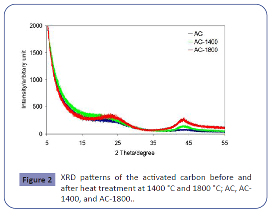
The structural properties of the activated carbon materials were further examined by XRD. (Fig. 2) displays the XRD patterns for AC, AC-1400 and AC-1800 samples. The XRD patterns indicate amorphous porous carbons. The AC sample showed a wide low intensity bump at around 2θ ≈ 24° and 44° which become narrower and higher in intensity for the heat treated samples. This shows that heat treating of the activated carbon resulted in some degree of order of the amorphous material which has likely resulted in closing of some micropres and therefore reduced surface area. This degree of order is also revealed in the electric conductivity of the samples (see Table 1). The activated carbon AC showed an electric conductivity of 2.6 S/cm, and after heat treating the carbon material at 1200 °C, the conductivity doubled. The best conductivity (8.3 S/cm) corresponds to the AC-1800 sample which is more than three times of the AC sample.
Electrochemical performance
The electrochemical impedance spectroscopy (EIS) measurements on the cells were performed at a DC bias of 0.2 V and a sinusoidal signal of 20 mV, over a frequency range of 1 MHz to 0.01 Hz.
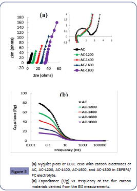
(Fig. 3(a)) shows the Nyquist plots of the EIS measurements on the five EDLC cells with AC, AC-1200, AC-1400, AC-1600, and AC- 1800 electrodes. The curves are separated by offsetting a small increment horizontally for a clearer view. They all show an almost vertical straight line in the low frequency region, indicating typical behaviour of a supercapacitor. The semi-circles in the inset of the (Fig. 3(a)) represent the internal resistance of the cells. It can be seen from these curves that the cell with the non heat treated activated carbon exhibits the largest internal resistance and heat treatment of the carbon material has decreased the resistance of the cells. This is due to the higher electrical conductivity of the heat treated samples as it is illustrated in Table 1. The effect of heat treatment temperature on the internal resistance of the EDLC cells is not apparent from the semi circles as the semi circles are very small and is hard to see any changes.
The length of the vertical region in (Fig. 3(a)) is inversely proportional to the capacitance of the carbon electrodes (Equation 1), and it increases with increasing heat treatment temperature. The capacitance of the carbon material in one electrode is derived from the Nyquist plot according to the following equation:
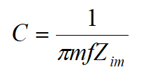
Where f is the frequency, Zim is the imaginary part of the impedance, and m is the mass of one electrode.
Capacitance vs. frequency curves are shown in (Fig. 3(b)). It can be seen that at the low frequency side (<10 Hz), the capacitance increases rapidly as the frequency decreases. At a certain frequency, the heat treated electrodes show lower capacity than the non heat treated one. Increasing the heat treatment temperature of the carbons resulted in a lower capacitance due to the lower surface area of the carbon.
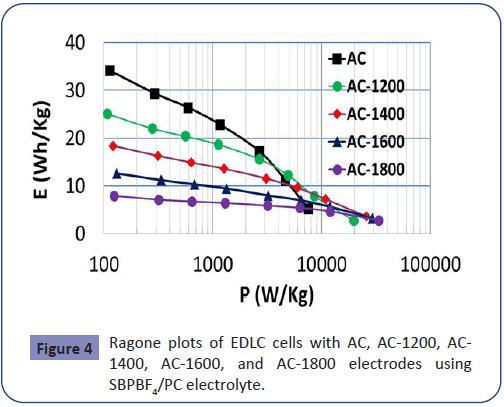
(Fig. 4) shows the Ragone plots of the EDLC cells with activated carbon electrodes of AC, AC-1200, AC-1400, AC-1600, and AC-1800 derived from the discharge curves of the galvanostatic charge/ discharge tests carried out in a potential range of 0-3 V at various constant currents. It can be seen from this figure that energy density of the cell with the non heat treated carbon (AC) at the low power end is higher than the cells with heat treated carbon electrodes. However, the energy density of the cell with the AC electrodes drops rapidly with increasing current. In addition, the cells with carbon electrodes heat treated at higher temperatures result in lower energy densities due to lower surface areas, but the decrease of the energy density with increasing power is slower for these cells. Therefore, heat treatment of the carbons has improved the power densities of the cells at high currents.
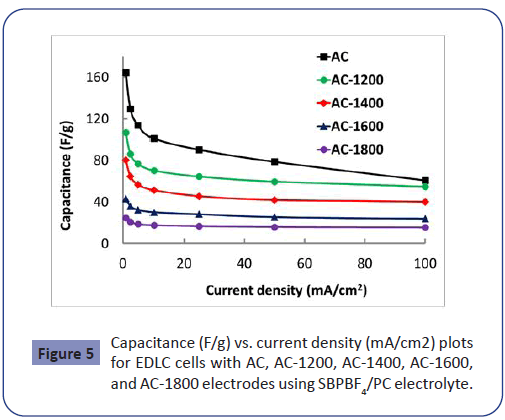
Capacitances of the EDLC cells derived from the discharge slope of the GCD curves at various current densities are illustrated at (Fig. 5). It can be seen from the curves that the capacitance of the cells is at the maximum at the lowest current and it decreases rapidly with increasing current density before reaching a plateau. In the cell with the activated carbon without any heat treatment (AC), the capacitance drops all the way from 164 F/g to 79 F/g without reaching a flat region, as the current increases from 1 mA/cm2 to 100 mA/cm2. For the cells with annealed carbon electrodes, the capacitance drops up to the current density of about 10 mA/cm2 and then it reaches a plateau. This indicates a good rate performance of the cells with the annealed carbon materia.
Conclusions
The effect of annealing (heat treatment) on the physical and electrochemical behaviour of the activated carbon material derived from phenolic resin was examined. Annealing of the activated carbon improved the electric conductivity and reduced the BET surface area. Annealing to only 1200 °C doubled the electric conductivity of the carbon. Increasing the heat treatment temperature resulted in closing up some of the porosity of the carbon and hence lowered the surface area. The limited surface areas of the annealed carbon materials restrict their capacitance and therefore energy performances of the EDLC cells. However, these materials stand out for their high power densities of up to 30 kW/kg at the energy density of ~3 Wh/kg. Therefore, for applications requiring high power density or rate performance, heat treatment of the activated carbon at a low temperature e.g. 1200 °C is recommended to achieve a high power density without a great sacrifice in the energy density.
Acknowledgment
This work has been funded by the European Commission FP7 project “AUTOSUPERCAP”.
References
- A. Burke (2007) R&D considerations for the performance and application of electrochemical capacitors. Electrochimica Acta 53 : 1083-1091.
- P. Simon and Y. Gogotsi (2008) Materials for electrochemical capacitors. Nature Materials 7 : 845-854.
- J.R. Kim, H.C. Boghani, N. Amini, K.-F. Aguey-Zinsou, I. Michie, et al. (2012) Porous anodes with helical flow pathways in bioelectrochemical systems: The effects of fluid dynamics and operating regimes. Journal of Power Sources 213 : 382-390.
- N. Amini, K.F. Aguey-Zinsou, Z.X. Guo (2011) Processing of strong and highly conductive carbon foams as electrode. Carbon 49 : 3857-3864.
- A. Szczurek, K. Jurewicz, G. Amaral-Labat, V. Fierro, A. Pizzi et al. (2010) Structure and electrochemical capacitance of carbon cryogels derived from phenol–formaldehyde resins. Carbon 48 : 3874-3883.
- M. Inagaki, H. Konno, and O. Tanaike (2010) Carbon materials for electrochemical capacitors. Journal of Power Sources, 195, pp. 7880-7903.
- T.A. Centeno, F. Stoeckli (2006) The role of textural characteristics and oxygen-containing surface groups in the supercapacitor performances of activated carbons. Electrochimica Acta 52 : 560-566.
- E. Frackowiak, G. Lota, J. Machnikowski, C. Vix-Guterl, F. Béguin (2006) Optimisation of supercapacitors using carbons with controlled nanotexture and nitrogen content. Electrochimica Acta 51: 2209-2214.
- J. Sanchez-Gonzalez, F. Stoeckli, T.A. Centeno (2011) The role of the electric conductivity of carbons in the electrochemical capacitor performance. Journal of Electroanalytical Chemistry 657 : 176-180.
- M. Sevilla, A.B. Fuertes (2013) Fabrication of porous carbon monoliths with a graphitic framework. Carbon 56 : 155-166.
- S.R. Tennison, O. Kozynchenko, V. Strelko, and A.J. Blackburn. (2008) Porous carbons, US Patent 2008032092.
- C. Lei, N. Amini, F. Markoulidis, P. Wilson, S. Tennison, C. Lekakou (2013) Activated carbon from phenolic resin with controlled mesoporosity for an electric double-layer capacitor (EDLC). Journal of Materials Chemistry 1 : 6037-6042.
- S. Brunauer, P.H. Emmett, E. Teller (1938) Adsorption of gases in multimolecular layers. Journal of the American Chemical Society 60 : 309-319.
- F. Stoeckli (1995) Porosity in carbons-characterization and applications, Editor: Patrick J. Arnold: London : 67-97.
- E.P. Barrett, L.G. Joyner, P.P. Halenda (1951) The Determination of Pore Volume and Area Distributions in Porous Substances. I. Computations from Nitrogen Isotherms. Journal of the American Chemical Society 73 : 373-380.
Open Access Journals
- Aquaculture & Veterinary Science
- Chemistry & Chemical Sciences
- Clinical Sciences
- Engineering
- General Science
- Genetics & Molecular Biology
- Health Care & Nursing
- Immunology & Microbiology
- Materials Science
- Mathematics & Physics
- Medical Sciences
- Neurology & Psychiatry
- Oncology & Cancer Science
- Pharmaceutical Sciences

